


By maddog2020 - Sat Jul 13, 2024 10:21 am
- Sat Jul 13, 2024 10:21 am
#271823
I'm actually making progress on the airbox, and wanted to document it here. I've posted some pics on FB, but here is where I'll be adding more detail.
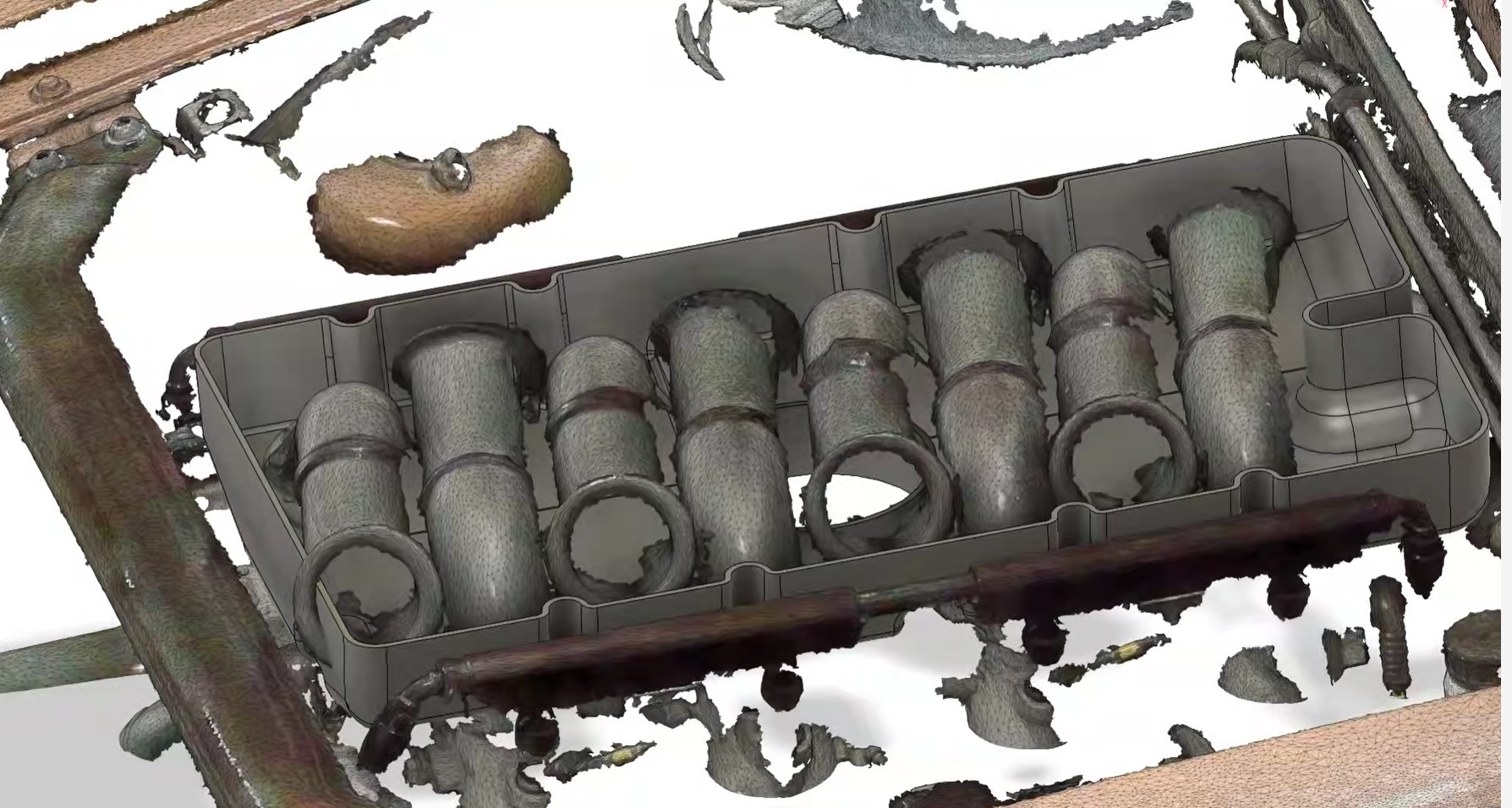
I've had access to Louie's airbox mold and decided a long time ago to go in my own direction, partly because of a discussion I had with Louie way back in the day. I asked him if you had to do the airbox all over again what would you do differently? He told me he'd put an access plate in the bottom of the box so he could service the linkages as well as the ability to access the idle bypass screws so things could be adjusted over time. I also wanted to go a different route on an air filter because I didn't want to tilt the radiator back, and put the air filter in front of the radiator as it gets much hotter here in Texas than Oregon where Louie lived. So about 15 years ago I started trying to make my own airbox from fiberglass. I knew what I wanted the airbox to look like, I just didn't have the skills to make it happen and that was one of the reasons the project languished for over a decade. 3D scanning and printing have come a long way in the last 5 years as well as the development of the materials used. It's time to make my vision into a reality.
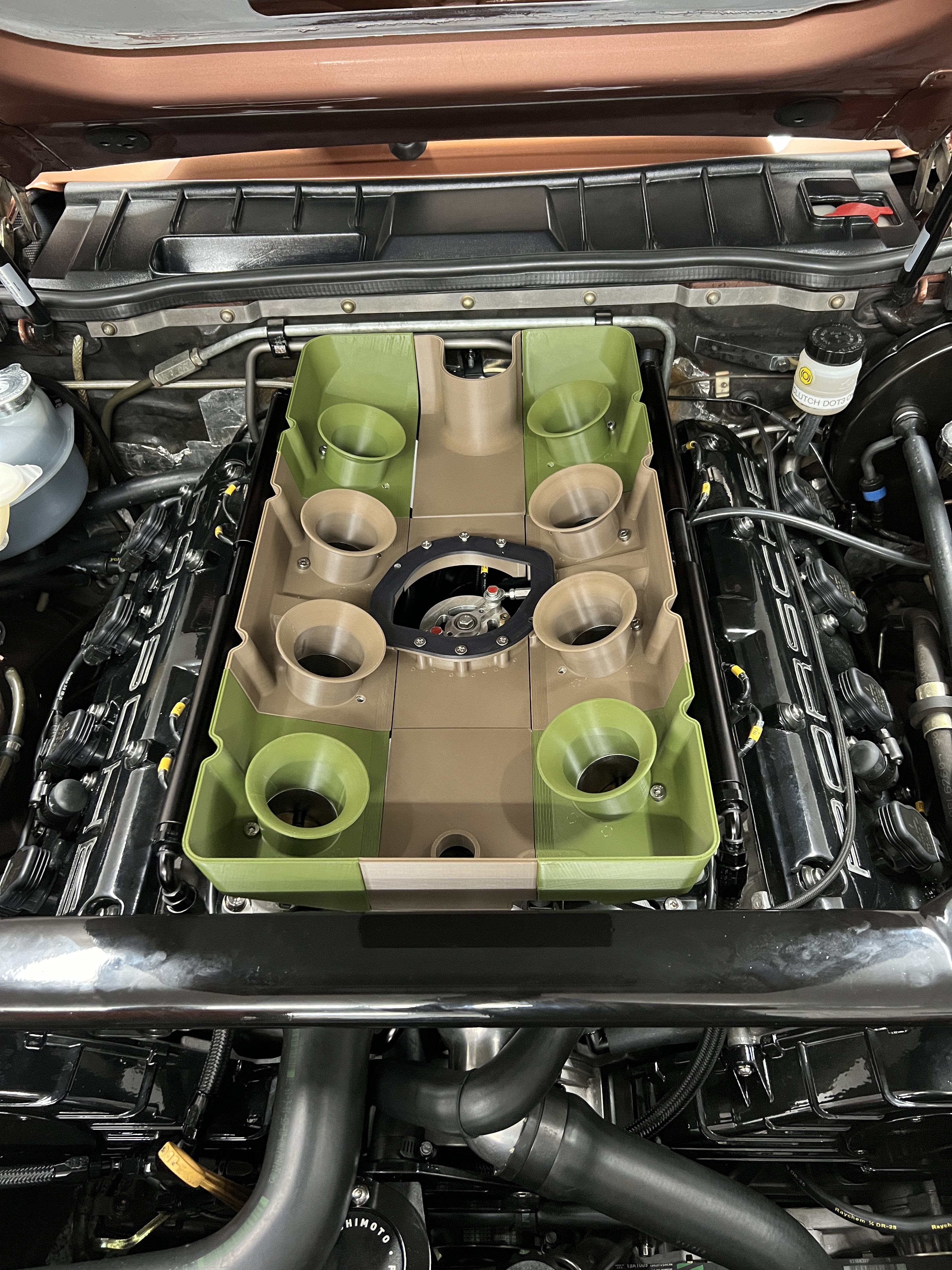
This is the 1st test fit of the lower airbox. some of the dimensions were off, and this is why you print and test fit stuff. This version is in pieces because to print a large piece like this will be very expensive. (about $1200) The second printing is already underway to correct some of the measurement issues.
I'm not ready to fully disclose my vision of the rest of the airbox. I will do so as I make progress. I've been floating ideas in my head for the airbox design since 2008 when I bought the ITB's and started planning. This started out as an idea, followed by crappy drawings, (I have the artistic ability of a rock) followed by wasted hours with fiberglass, and now working with a guy who has scanned my entire engine bay, and is doing the CAD and 3D printing work based on my designs.
so here we go.
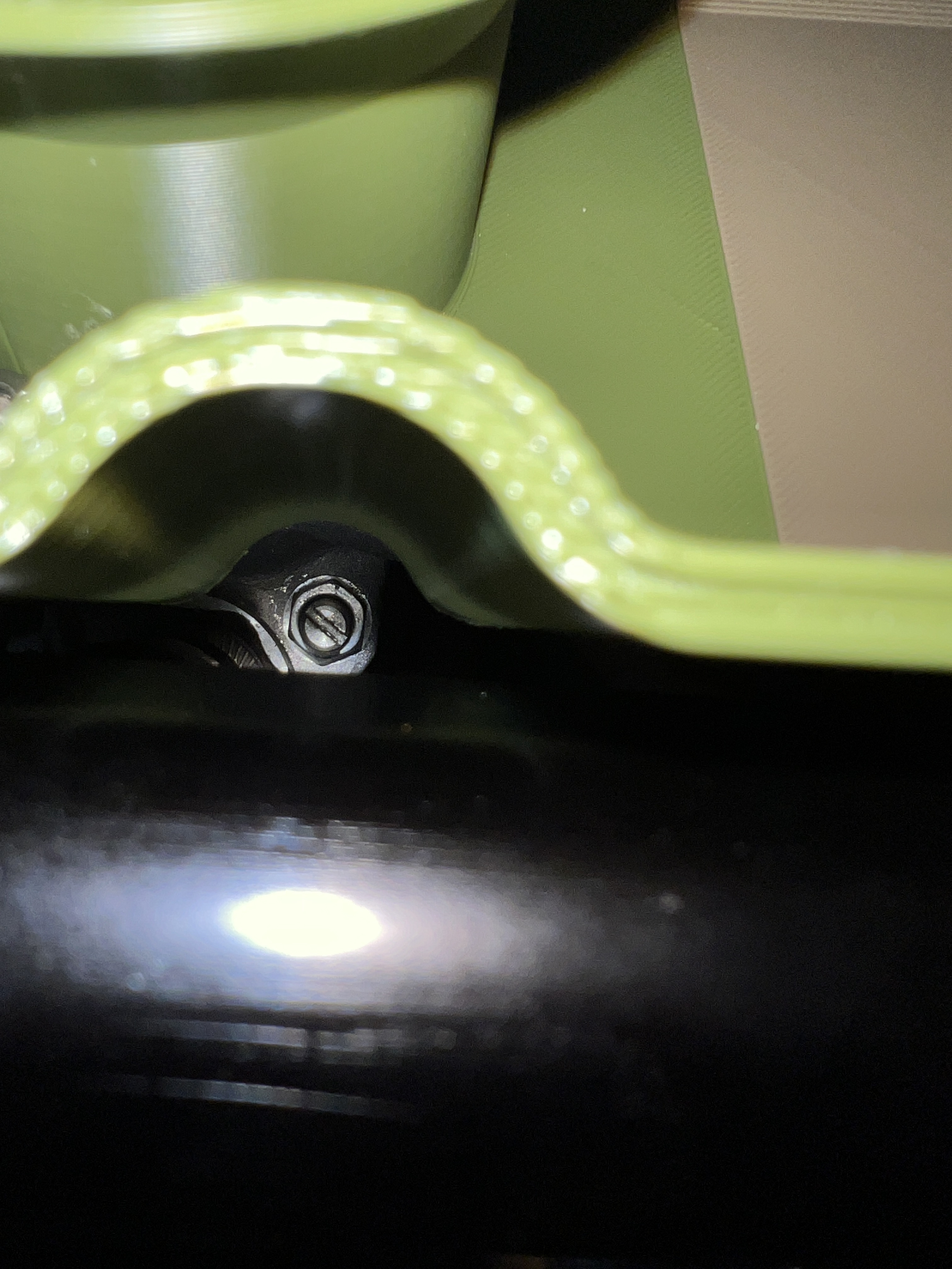
This provides access to the Fuel Pressure Regulator
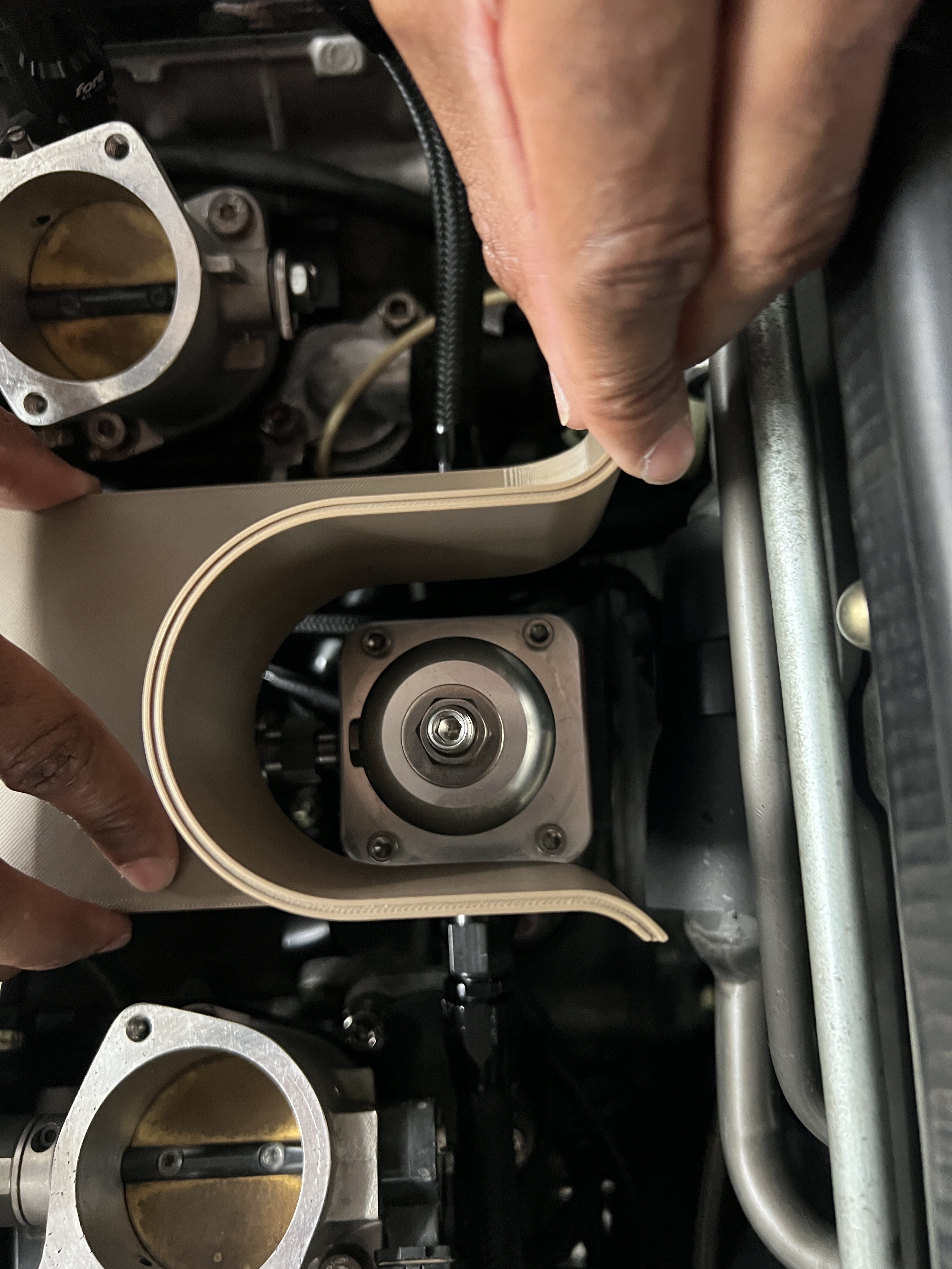
Linkage access
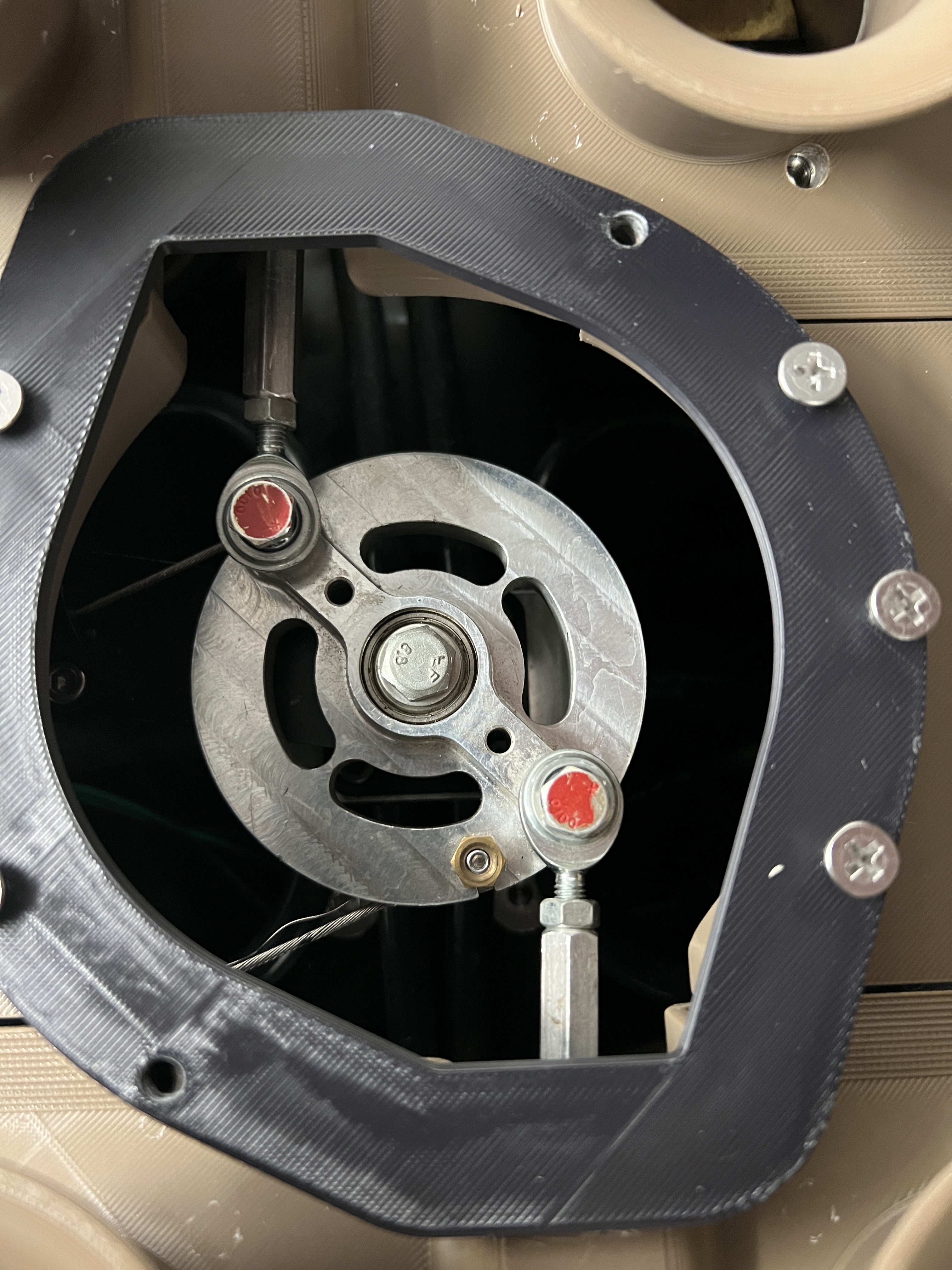
Access for the idle bypass
I've had access to Louie's airbox mold and decided a long time ago to go in my own direction, partly because of a discussion I had with Louie way back in the day. I asked him if you had to do the airbox all over again what would you do differently? He told me he'd put an access plate in the bottom of the box so he could service the linkages as well as the ability to access the idle bypass screws so things could be adjusted over time. I also wanted to go a different route on an air filter because I didn't want to tilt the radiator back, and put the air filter in front of the radiator as it gets much hotter here in Texas than Oregon where Louie lived. So about 15 years ago I started trying to make my own airbox from fiberglass. I knew what I wanted the airbox to look like, I just didn't have the skills to make it happen and that was one of the reasons the project languished for over a decade. 3D scanning and printing have come a long way in the last 5 years as well as the development of the materials used. It's time to make my vision into a reality.
This is the 1st test fit of the lower airbox. some of the dimensions were off, and this is why you print and test fit stuff. This version is in pieces because to print a large piece like this will be very expensive. (about $1200) The second printing is already underway to correct some of the measurement issues.
I'm not ready to fully disclose my vision of the rest of the airbox. I will do so as I make progress. I've been floating ideas in my head for the airbox design since 2008 when I bought the ITB's and started planning. This started out as an idea, followed by crappy drawings, (I have the artistic ability of a rock) followed by wasted hours with fiberglass, and now working with a guy who has scanned my entire engine bay, and is doing the CAD and 3D printing work based on my designs.
so here we go.
This provides access to the Fuel Pressure Regulator
Linkage access
Access for the idle bypass
h2pmr, Dimitri928 liked this
 - By h2pmr
 - By N_Jay
 - By NSXguy